
![elevation bridge [Converted]](https://cdn.myportfolio.com/e6d23a7b-de6b-4dae-bd6f-1f966618317e/3eaa12c6-364b-4c54-8632-b35d268f20a5_rw_1920.jpg?h=d2a7f0bc847f5d6259640368d6961e57)
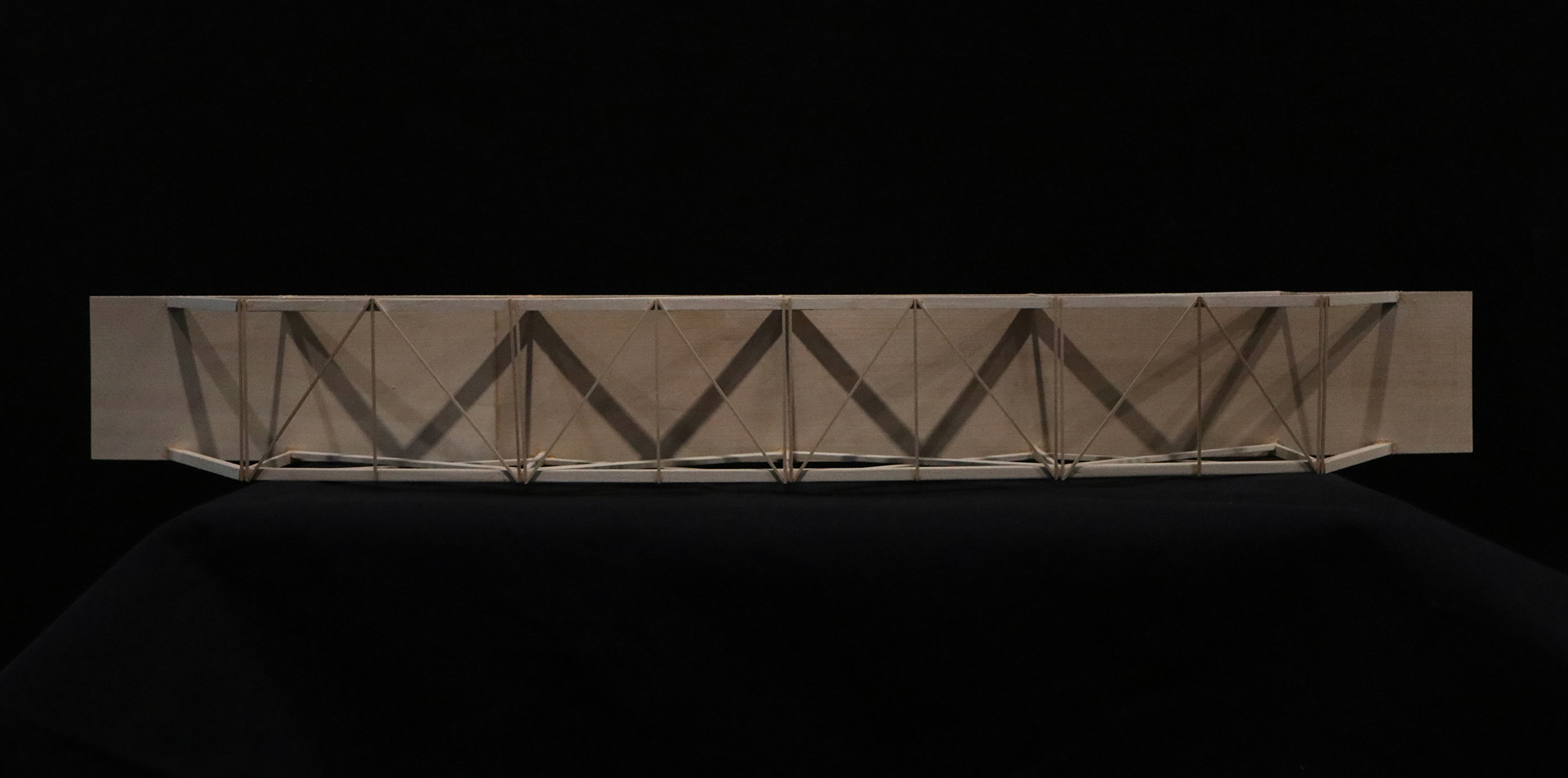
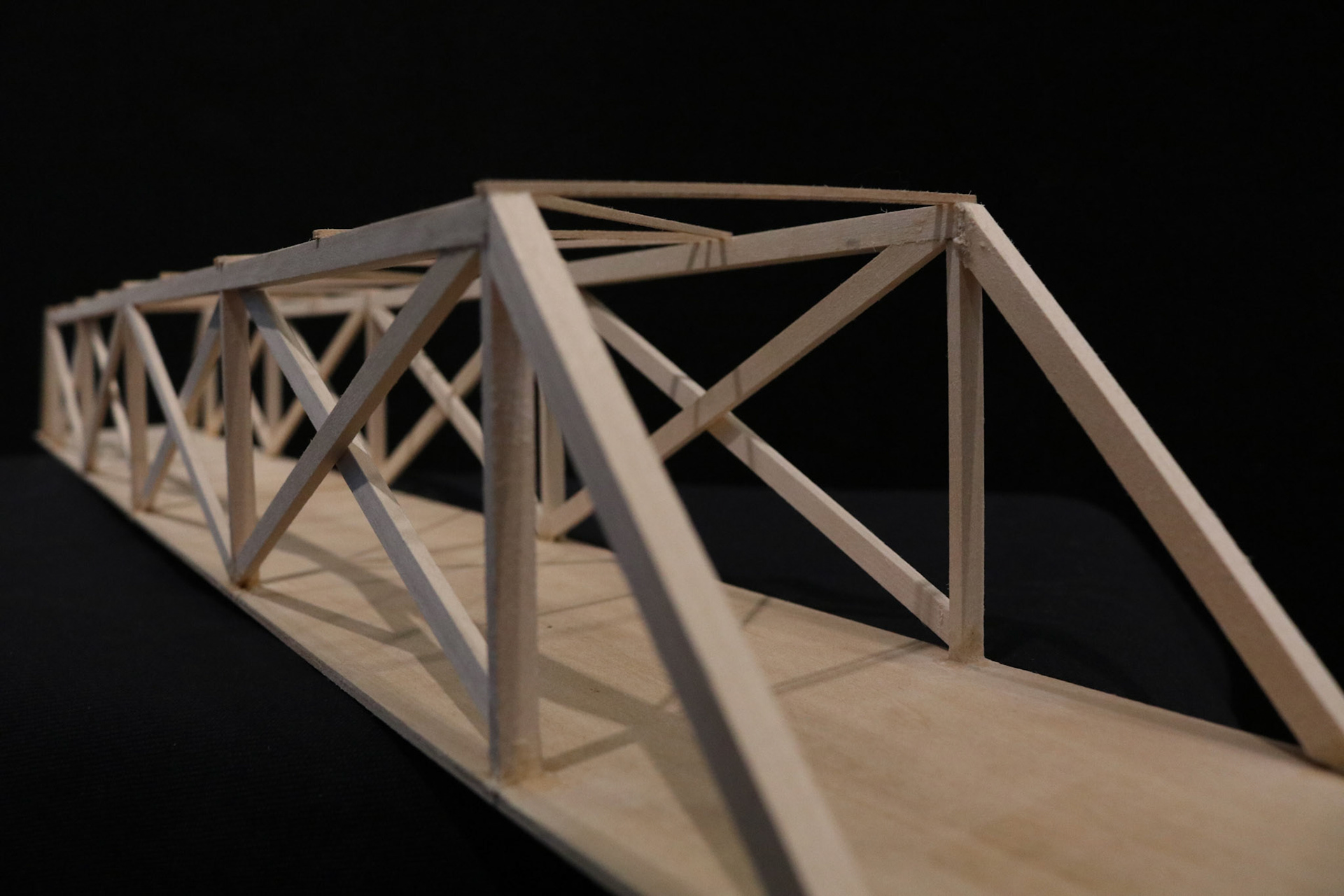
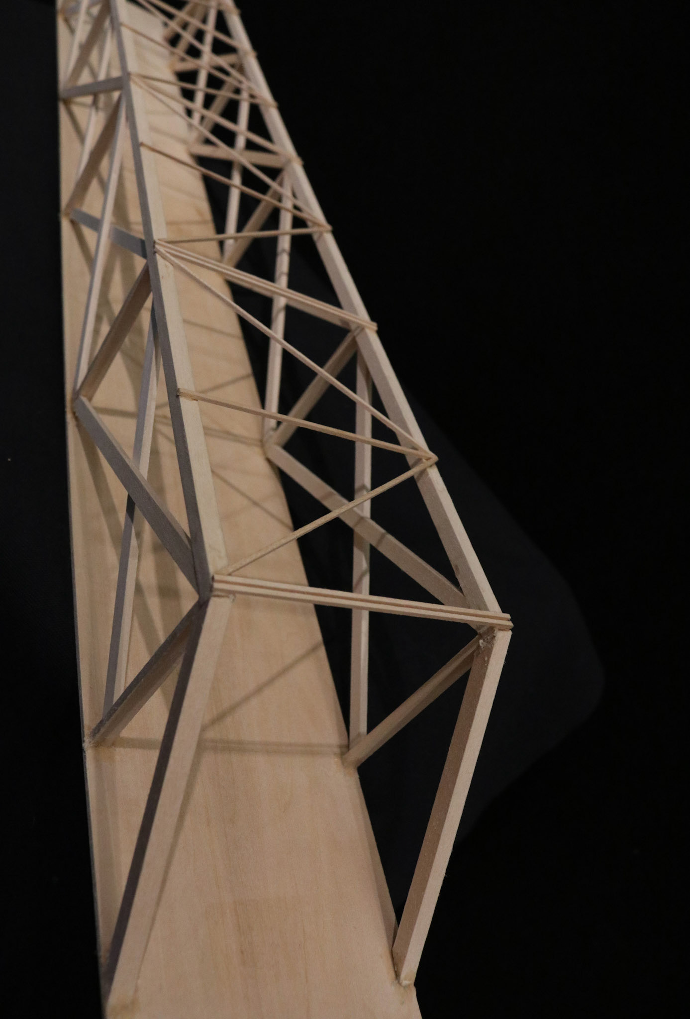
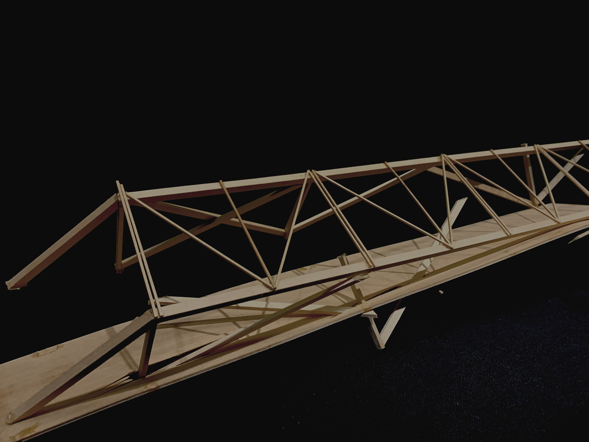
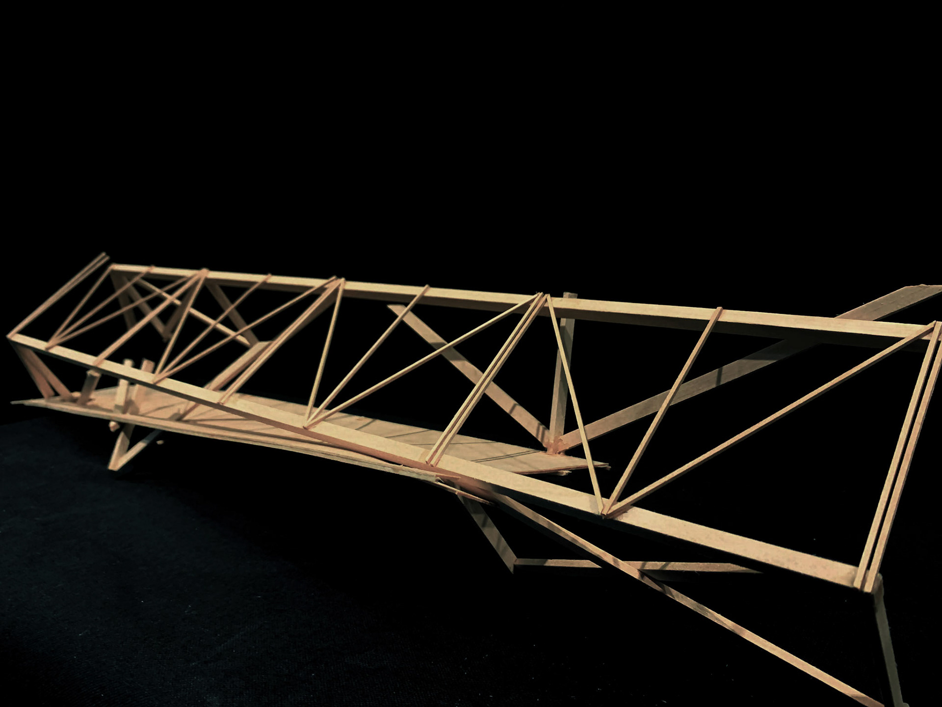
Through this project, we had the task of creating a structurally sound truss bridge that would maximize the load capacity to bridge weight ratio. We first started by researching possible precedence for our design. Specifically looking at truss profiles used on small two-lane bridge projects, we wanted to gain a better understanding of how the systems transferred loads throughout the structure. We also found it helpful to look at alternative structural methods such as cross-bracing and the influence of different geometries. With several design constraints, including a 160 feet span, 52 feet depth, and an 8-inch maximum slab, we decided to carry forward with a 32-foot height. We decided to go ahead with a variation of a Howe truss as the primary trusses along the sides of the bridge. On the underside of the slab, a variation of the Warren truss creates additional support. However, after designing and building one truss system, we discovered we would not meet the 4-ounce weight maximum. Revising our design, we decided to lower the truss height to 16 feet, allowing us to remain under the maximum weight. Changing our panel height affected its overall geometry by expanding the panel width to height ratio, but allowed us to add additional supports. We later added a truss system spanning over and connecting the primary trusses. Upon the testing day, our truss bridge weighed 3.90 ounces and was able to hold a maximum weight of 30 pounds before failure. When placing our structure on the platform, we were initially concerned about the minimal surface area and thickness of the slab extending over the platform supports. When assessing our bridge post-testing, we found that many of the trusses were still intact. Video evidence showed that the breakage started at the seam of the bridge slab, where two individual wooden decks were attached. The failure of the slab seems to be responsible for truss collapsing into itself, causing the truss systems to puncture through the slab. The supporting cross bracing located underneath also failed at the point of breakage. While our bridge had been able to hold 30 pounds of weight successfully, there are improvements needed in our design. As we discussed earlier, our bridge had a weak point at the ends of the trusses and the seam of the deck. Our structure might have been able to hold greater weight if we had added additional bracing at the ends. For those members would have been able to help counter the stress brought by the additional weight. Secondly, if we had been able to find a better way to join the two connecting slabs, we may have had more success. The connection between the two slabs may have been able to hold an increased amount of weight with these adjustments. Smaller adjustments may have helped, such as a greater thickness of the slab overhang. Another option could be increasing the height of the center of our truss structure, thus increasing the center of gravity on the bridge and allowing the bridge to become stronger. However, due to our weight limit sitting at 3.90 oz, we only had about 0.10 ounces to spare. Making these changes would require losing weight elsewhere.


![elevation bridge [Converted]](https://cdn.myportfolio.com/e6d23a7b-de6b-4dae-bd6f-1f966618317e/3eaa12c6-364b-4c54-8632-b35d268f20a5_rw_1920.jpg?h=d2a7f0bc847f5d6259640368d6961e57)